Depending upon mission needs, the ship can be outfitted with different modules that include:
■Manned aircraft, such as a helicopter and flight crew
■Amphivious assault ship armed with laser, SAM and anti ship missles
Manned and Unmanned Combat Air Vehicle
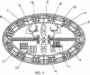
The entire document is posted on panaceauniversity.org/D8.pdf, here is a short description of what the “spaceship” does and how it can be built, as described by Patrick J. Kelly (update: the document I mentioned in 2008 doesn’t exist anymore) :
“Tesla performed an experiment in which he applied high-voltage high-frequency alternating current to a pair of parallel metal plates. He found that the ‘space’ between the plates became what he described as “solid-state” exhibiting the attributes of mass, inertia and momentum. That is, the area transformed into a state against which a mechanical push could be exerted. This implied that, using this technique, it should be possible to produce a spaceship drive anywhere in space, if the mechanism for thrusting against the ‘solid-state’ space could be determined. Further experiments convinced Tesla that powerful electromagnetic waves could be used to push against (and pull against) what appears to be ’empty space’. The drive principle is based on the Hall-effect used in semiconductor magnetic sensors, and is called the magnetohydrodynamic (“MHD”) effect. This might be illustrated like this:
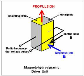
Here, a box is constructed with two metal plates forming opposite sides and two insulating plates holding them in position and surrounding an area of ‘space’. High-frequency, high-voltage alternating current is applied to the metal plates and this creates an electric field “E” acting between the plates as shown in black.
A magnetic field “B” is generated by the electrical field. The magnetic field acts at right-angles to the electric field, as shown in blue. These two fields produce a propulsion thrust “F” shown in red in the diagram. This propulsion force is not produced by ejecting any matter out of the box, instead, it is produced by a reaction against the ‘solid-state’ condition of space-time caused by the high-frequency electromagnetic pulsing of that area of space. This is enormously more effective than a jet engine. The thrust increases with the fourth power of the frequency, so if you double the frequency, the effect is sixteen times greater.
To put this into perspective, consider the force being applied against gravity to lift an object into the air. The force pulling the object downwards is gravity and its strength is given by:
Gravitational force:
F = g x M x m / r2
where
G is the gravitational constant (6.672 x 10⁻⁸ cm3 g-1 s-2)
M is the mass of the first body
How do these forces compare? Well, the electromagnetic force is stronger than the gravitational force by a factor of about 2,200,000,000,000,000,000,000,000,000,000,000,000,000 times. That number (2.2 x 1039) is too big for anybody to really visualise, so let me put it another way.
MATERIALS OF CONSTRUCTION
For anti gravity propulsion Dielectric Materials or, insulating material which is a very poor conductor of electric current is needed for the body of the ship. When dielectrics are placed in an electric field, practically no current flows in them because, unlike metals, they have no loosely bound, or free, electrons that may drift through the material. Instead, electric polarization occurs.
Super wood that is so strong it can stop a bullet and is as robust as STEEL could be the building material of the ship. Engineers boiled blocks of regular wood in a chemical solution to soften them. These were then pressed between heated metal plates at extreme pressures. This increasing its density threefold while reducing its thickness by 20 per cent. The resulting material was able to stop a projectile in its tracks during tests. Super wood that is as robust as steel and six times lighter could be a renewable construction material for the future, according to scientists. Planks of the reinforced lumber, which researchers have compared to carbon-fibre, could be used to create anything from buildings and cars to bullet proof jackets. Scientists put the material through its paces in ballistic tests and found that a laminated version could even stop a projectile in its tracks.
The first X-45A Unmanned Combat Air Vehicle (UCAV) technology demonstrator completed its sixth flight on Dec. 19, 2002, raising its landing gear in flight for the first time. The X-45A flew for 40 minutes and reached an airspeed of 195 knots and an altitude of 7,500 feet.
Credits: NASA Photo / Jim Ross Flying ships invulnerable to super cavitating torpedos
The Joint Unmanned Combat Air Systems (J-UCAS) program was a joint DARPA/Air Force/Navy effort to demonstrate the technical feasibility, utility and value for a networked system of high performance, unmanned air vehicles to effectively and affordably prosecute 21st century combat missions, including
suppression of enemy air defenses, surveillance, and precision strike within the emerging global command and control architecture. One of the aircraft systems evaluated was the Boeing X-45A, for which NASA Dryden provided technical expertise and support facilities.
There is a very competitive large aircraft market as illustrated by the AirBus decision to produce the A3XX that could carry about 650 people on two decks. The intra-Asian market is another area that can utilize high density loading. They are already doing it with Boeing Super 747s rigged for full economy seating to haul 550 people over the short distances between cities. The trade off is less fuel, but it isn’t needed for the short runs. This is going to be a problem for the Chinese in about 10 years as they become more affluent and want to travel throughout their country.
Another aspect of large aircraft design is the ability to adapt it to the all cargo market. Al didn’t hasn’t really seen the full logic behind the idea yet, but NASA is pursuing it. With used Boeing 747s available at relatively low prices, along with other smaller aircraft that are readily available, the market for a new large cargo hauler may not be as great as expected by NASA. Another aspect of large aircraft design is the ability to adapt it to the all cargo market. Al didn’t hasn’t really seen the full logic behind the idea yet, but NASA is pursuing it. With used Boeing 747s available at relatively low prices, along with other smaller aircraft that are readily available, the market for a new large cargo hauler may not be as great as expected by NASA. However, the military gets interested it design and helps defray some of the startup costs, then the picture for the commercial markets could change.
For the cost of a LCS below the Navy can have a 400 mph aircraft carrier $ 440M
Carbon fibre planes: Lighter and stronger by design
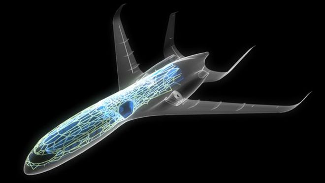 AIRBUS
'Mould all the parts together'
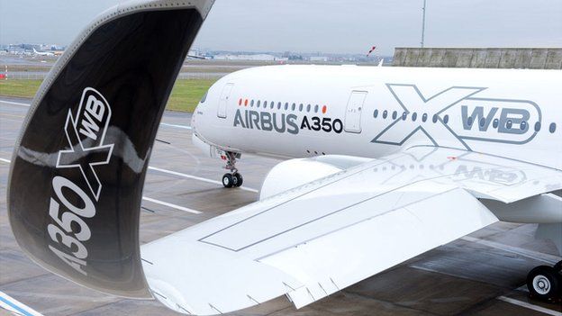 AIRBUS
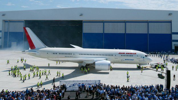 BOEING
Growing use of composites
Future designs
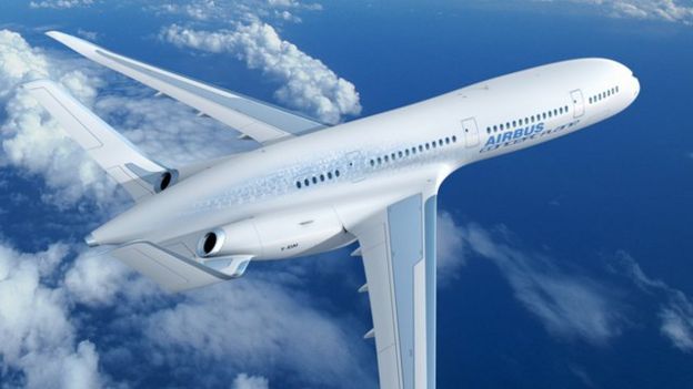 AIRBUS
On using carbon fibre
One of the worst misconceptions of carbon fiber composites is the thought that a little bit of carbon will add a lot of strength. Not so.
When you engineer a laminate of any sort with materials of different strengths and stiffnesses, you need to take into account two stiffness factors: E = modulus of elasticity of the material (Young's Modulus), and I = moment of inertia of the laminate cross section. The bending and stress behavior depends on the product ExI. If two materials of vastly different stiffness are bonded together in a working structure, in this case say wood and carbon fiber, then an even match and complementary bending behavior will be when the ExI of the wood equals the ExI of the carbon. E of wood can be anywhere from 500,000 psi to 2,000,000 psi, depending on the species of wood. Carbon fiber, on the other hand, can have an E anywhere from about 7,000,000 psi to 14,000,000 psi--many times greater than wood. In a wood rudder, the I of the rudder cross-section can be relatively high because the primary determinant for I is the thickness of the section, raised to the third power. With only a strip of carbon fiber within the laminate, however, the width of the carbon tape is generally not enough and the thickness of the carbon is really, really thin; and while the tape's distance away from the center of the rudder section is important and adds to its I, usually the I for just a strip of carbon is not anywhere near enough to add sufficient strength and stiffness to the section. The I is really, really small.
So what I am trying to say is that if you are going to add carbon fiber to a rudder, you had better be prepared add a lot of carbon fiber over the whole skin in order to make a significant difference. Stress in the laminate is always going to build up faster in the stiffer material (the one with the higher E) and if you don't have enough material in there to handle the stress that it is going to attract, then you have a potential for a real failure.
This is exactly what happened to the carbon fiber and aluminum rudder stocks for so many sailboats in the 1979 Fastnet Race disaster. Aluminum rudder stocks were shaved down thinner a bit (to save weight) and reinforced with just a small amount of carbon on the outside. Not enough carbon was there, yet the carbon tried to assume the lion's share of the load because it was stiffer than the aluminum. The carbon fiber failed when it got over-stressed, and once the carbon failed, there wasn't enough aluminum section left to handle the loads, and so the aluminum failed.
Finally, one of the biggest follies I have seen over the years is when boat builders use narrow strips of carbon fiber tape laid up into the hulls of boats in a cage like pattern. They think that this carbon "cage" will add a lot of strength to the hull, making it very stiff, like an internal framework. Nothing could be further from the truth. Generally, there is not enough carbon in there to do anything at all, the builders are simply throwing away money. If you want to make a really strong carbon fiber hull, then you have to have whole layers of carbon fiber spread throughout the laminate, and on both sides of the core if there is a core.
The biggest kicker is to take the body of theairplane and morf it with the wing, then you get a body that produces lift merging with the spanloader idea. You can’t take it to the point of a true flying wing due to the added wing area at the outboard ends creating too much
This was all started by a design study in 1989 by Dr. Dennis Bushnell, Chief Scientist at NASA Langley. He foresaw the need for a commercial aircraft that could carry 800 passengers over 7000nm and a speed of .85 Mach. This was the result of that design study which was originally McDonnell Douglas’.
One of the more interesting facets of this design was the position of the engine inlets. Since they are right down on the wing surface, they are ingesting the boundary layer so any airflow sucked into the engines can be ignored as drag. This gives a huge increase in the L/D due to the decrease in drag. There are also a lot of control surfaces on this version, however, the larger inner surface has been eliminated in follow-on designs. As part of what Al was talking about earlier, notice the 290’ span that won’t fit into the current passenger terminal infrastructure. This makes this configuration non-viable as a solution to the high density passenger carrying BWB.
The other obvious thing in the pictures are the really heavy structural walls between the compartments. Al now went on to answer Ralph Wilcox’s question about how hard is it to pressurize a square box versus a cylinder. The heavy walls are one of the ways and due this extra weight they also cut into the ultimate potential gains Al talked about in the first part of his presentation. However, he also commented that it is expected enough gains will be made on the aerodynamic side to offset the extra structural weight. Gavin asked about putting a series of round section within the wing to carry the pressurization loads. Al commented that this was looked at, but in the final analysis it was determined that weight wise it is better with the current design parameters. He did note there are some fatigue questions that still need to be worked out before there is any commitment to building something like the BWB.
Gavin ask Al whether or not the airlines would be behind these types of changes in aircraft design. Al commented that in his opinion changes in the environmental laws will probably create the need for such aircraft to meet things like emission standards. If airport and airspace congestion rules are changed, the aircraft will have to change and the airlines will go along because they will have too.
The challenges included: structures and materials; aero-structural integration; aerodynamics; controls; propulsion-airframe integration; systems integration and; infrastructure. Structures is back to the pressurization issues and the integration issue revolves around making the structure clean enough to work aerodynamically and achieve the savings potential.
Aerodynamics is a separate issue from the aerostructures. Imagine that this design has an elliptical span load associated with it, so that is the minimum induced drag for this vehicle. Then think about the lift coefficient that needs to be produced for this type of wing. Since the span load is chord dependent the center body section with its wide chord had no problem meeting the requirements. But as you move out towards the tips you reach a pinch point where the chord narrows sharply. The problem is going to tip stalling due to the high taper ratio and the loading out there. This is a problem for the aerodynamicist since the aircraft must takeoff and land. This means you need to generate high lift coefficients, which puts you close to the stall, which is also close to the departure. Of course the last thing you want is a passenger aircraft with bad departure characteristics, so how do you get the lift coefficients at the pinch point to avoid these problems or at least degrade elegantly so you don’t lose control of the airplane.
Ralph asked the question about boundary layer control at that point on the wing. Al commented that it had been looked at and there was still a problem even using vortex generators. Boeing went to slats on the outboard section since this would generate a lot of lift on this portion of the wing. The disadvantage of this system is that slots and slats have really bad hysterisous effects, so once stalled it might be hard to get back. NASA is still looking into this area.
On systems integration, Al noted that this area is becoming more and more complicated. This is the digital fly-by-wire systems so you can control the way in which the aircraft reacts to the control inputs. This particular design has a nose slice just before reaching the stall, so some method is needed prevent in inadvertent departure. The digital controls with its accelerometers and other sensors feeding back information, the control surfaces in the affected area can be deployed upward to decrease the span loading and move it inboard. This will prevent the airplane from departing, but it is so sensitive that any external changes can have major effects on the departure characteristics.
Gavin asked a question about what types of construction techniques would be used for this aircraft. Al said it was planned to be built by bending tin and used the 747 as an example. If you look at the outer wing panels on the 747 and compare them to the same panels on the BWB you find they are very similar. Since the BWB was originally a McDonnell Douglas design, the outer wing sections were based on the DC-12 which was never produced because of the buyout by Boeing. This then became a good starting point so the center body construction problems became the focal point of further development.
For Flying Aircraft Carriers, the best defensive weapon is a 150kw laser
US military will use SUPER LASERS with 150kW of power to knock out enemy missiles by 2020
- A 60 kW laser weapon will soon be installed on a US Army truck
- But experts believe that weapons with 150 kW power could be used by 2020
- Such a laser could knock out a missile sideways on, where it is most vulnerable
With metal airframes there is an I-beam with a plate on the top, the skin, that is riveted in. It turns out that due to the factors of give, flex and friction the actual frequency actually, when tested, comes out lower than the prediction. This goes back to the fly-by-wire system where the pilot can make a jerk input to the stick which would give an almost perfect square wave input to the system. The system looks at it as a change to the angle of attack. In most airplanes the change would occur gracefully with some overshoot and then stabilize out, which is the short period frequency. If this frequency is the same frequency as the structural wing bending the aircraft will catastrophically fail. The pilot can’t be told not to make these types of control inputs, especially if they are fighting an aircraft in turbulence while landing.
Now we bring in the composite structure. Some composites joints are glued together and other are not, so in some cases there are butt joints where the load transfers are harder to calculate. In tension and compression there is pretty good data, but not in the bending. Apparently the joints don’t handle the stresses that same way in each direction so this makes the calculation much more difficult. At this point in time there just isn’t a lot of experience on how to handle these types of joints on airplanes. This is due to the load having to transfer from one skin, through the flange or other connecting structure, to the other skin. Since the cloth fibers are not running continuously along the known stress line, the calculations become much more complex.
Another major issue that will need to be worked in the future, but is not a top priority at this point, is the outer surface “bulging” that will occur as the aircraft is pressurized. These bulges will form in-between each of the main structural bulkheads forming the passenger compartments. Obviously this will deform the elegant cruise airfoil shape that is being planned, so it has to be taken into consideration in the design. When doing this with composites it becomes even more difficult due to the lack of experience in this area.
Along with the digital fly-by-wire comes the all electric subsystems; everything is electronic onboard the aircraft. This is a very common in the military in aircraft like the Air Force’s F-16, but is just now starting to become more prevalent in commercial aircraft. Doug Fronius asked if this meant no hydraulics and Al commented that there were still hydraulic actuators being controlled electrically at the site of the control surface. Doug noted that the next generation of military aircraft coming along will truly be all-electric with no hydraulic subsystems. Although there are some supporting subsystems on commercial aircraft at the present time, both Doug and Al indicated all-electric main systems were probably a long way off.
Dominique Viellard asked about the thickness of the boundary layer. Al said he wasn’t sure about the numbers, but did estimate it could be a couple of feet thick at the rear of the centerbody section of the wing. The chord at this point is close to 160’, so Al wouldn’t be surprised if the it reached these larger thicknesses.
Ralph Wilcox asked about what the wing loading would be for this type of wing. Al commented that when you go to a flying wing you need to bring the numbers back down from what you would have for a conventional aircraft. So instead of having the 105-120 numbers for things like the Boeing 7X7 series, you need something like 95-105. This is easier to do on the BWB since you have so much more wing area.
Gavin Slater asked about the problems associated with boundary layer ingestion (BLI) on the three engines at the back of the aircraft. Engines don’t like to see a lot of distortion at the compressor face and, this will become even worse at high angles of attack. The boundary layer will get much thicker and it presents many problems in designing ducts or making changes to the engines themselves. (ed. – This problem has led to a different engine configuration as shown below. The engines have been moved up on pylons to get them out of the boundary layer flow at all times.)
The large number of control surfaces presented their own unique troubles. Since any one control deflecting upward will cause the aircraft pitch up the question became one of how best to control the mixture of movements. They had to determine whether there were any pitfalls like airflow separation as the controls moved in differing amounts. Some of these questions are being answered through wind tunnel tests.
Andy asked Al what caused the phenomenon on the model where the control surfaces appeared to be flopping around during ground taxi. Al indicated the controls were responding to the inputs from onboard sensors being activated by bumps in the taxiway. Due to the low airspeed associated with taxiing, the control deflections to correct the sensed conditions were large and therefore drove the surfaces to their stops. The electric actuators are very fast, so it appears the surfaces are just really loose on the hinges. Al noted this occurs on current fly-by-wire aircraft in the military as they taxi, you just have to look closely to see it.
As Al continued, he noted one of the big questions revolves around something they call “behavior quantification”; how does the aircraft behave, what does it do. They have problems with stall, the aeroelastic properties cause dive problems during the pull out, and a mach buffet with an “ugly” tuck. Then there is the issue of engine out performance since it doesn’t have real strong directional stability. If you loose an engine, what is the Vmca really going to be? The last issue is stability margin in terms of pitch, lateral and overall directional control.
Up to this point everything that he had been talking about revolved around the 800 passenger version that was studied under a NASA contract that ended in 1996. At that time the Douglas division of
One of the first things you notice on this design is the engines having been raised out of the boundary layer flow. This was the fastest and easiest way to solve the inlet and compressor problems trying to deal with the turbulent flow off the rear of the wing, especially in high angle of attack flight. Since this was going to be one of the hardest problems to solve and may not have been economically feasible, the simpler approach was taken.
Although hard to see in the drawing, the control surfaces are spread out differently. There are now 16 control surfaces instead of 22, but it still have the split elevons in the last four outboard elevons, with the outermost two being ganged together. It is all electric with no hydraulics on board, using control actuators taken from an air-launched munitions program. These actuators are designed to work for 90 seconds, yet the test vehicle is being designed to last for 100 hours, so there was another problem than needed to be worked out. It turned out that the actuators were way over designed for the munitions application and probably would last much longer in the less demanding environment of the BWB. The model was also being built in such a manner that the actuators could be easily removed if they showed signs of failure.
The next problem they had to overcome is which digital controller would drive which control surfaces. To maintain a minimum level of redundancy, each controller must drive actuators at different parts of the wing so the failure of one controller will not bring the aircraft down. A little later there was a discussion between Al and Doug about the software NASA is using so the controllers know which one takes the lead and how the entire system determines when the lead controller is actually have a problem and needs to be relieved by a secondary unit. This got a little deep on the technology side, so not much more will be covered here.
Power will be provided by three Williams turbojet engines from target drones that are designed to operate for about 10 hours. The same issues came up here as with the actuators, plus there was no low idle setting (below 90 lbs.) on the fuel control (the Navy didn’t need low idle for in-flight launch so it was not designed in by Williams). The spool up time was also not acceptable since the engine would take 33 seconds from idle to the full thrust of 240 lbs. After long discussion with Williams and a lot of money, NASA got their supply of engines with a 35 lb. idle setting and a much faster response time from idle to full power. Since the test vehicle only needs about 190-200 lbs. per engine, a detent was placed on the pilot’s throttle console to limit thrust at 200 lbs. This will make the engines last well beyond the 10 hours. The pilot will have the ability to remove the detent in the event of an engine failure and more power is needed from the remaining engines.
The wing does have slats on the leading edge, however, they do not have actuators so are locked in a fixed position depending on the type of test to be conducted. The original plan called for a ballistic recover chute to save the model, but that has been removed and replaced by triple redundancy in the control software (remember spreading out the control surfaces between controllers) and dual redundancy on hardware. The various antennas will be integrated into the structure to try and keep the surface as clean as possible. There will be a spin recovery chute since plans call for spin testing of this model, along with attempts to make it tumble.
Al mentioned that the weights shown in the slide were dynamically scaled to the commercial, full size version. He gave the example of scaling something down by one half, which results in a piece of hardware that has one quarter of the area, one eighth the volume and one eighth the mass (dynamic scaling). The other scaling factor is moment of inertia. NASA has a very specific set of weights, moments of inertia, area and size targets for this project. The 2,700 lbs. represents the scaled maximum takeoff weight of the full size aircraft. On the other hand, the 2,300 lbs. minimum (empty) weight is well above the truly scaled 1,300 lbs. This is due to the fact you can’t always economically scale down things like actuators and other types of hardware, computer systems and other instrumentation. They are not satisfied with the high weight and are trying to get it down below 2,000 lbs., but they are not sure this will happen. The construction is all carbon fiber and Al gave as an example of weight savings the winglet’s vertical surfaces. These have a design weight of 7 oz. including all hinges, horns, ribs, etc., and will have to withstand a max speed of 140 knots. Based on what they know now it doesn’t look like they will make that weight, but at least it will be the minimum they can make it.
One other thing he wanted to cover on this slide was the relationship between the 14.2% scaling factor and the 35’ wing span. If you do the math they don’t come out to the 289’ of the model he was talking about at the beginning the presentation. That’s because this model is for the smaller, 450 passenger, single-deck version that Boeing is working towards. This is still bigger than a current B-747, so many of the earlier noted problems regarding infrastructure still apply.
The lower right portion of the slide shows the general layout of the test model with fuel tanks and elevons located in and one the center section. The wings will be separate which is mainly so the model can be shipped more easily with the plan being to use a large motorhome that doesn’t have any interior (just a big box on wheels). Alternate shipping plans include using Air Force C-17 training missions and, as a last resort, paying to ship it on a Super Guppy.
What NASA is doing here is looking at the flight characteristics of the BWB class of vehicles. Although the test model doesn’t reflect the latest developments in design changes (as a result of freezing the design for the models purposes), all the test data will be extrapolated to the latest versions using data obtained over the life of the project.
At this point Al took a few minutes to explain a little more about dynamic scaling. If everything goes as planned, the model’s scaling will exactly duplicate the aerodynamic forces are work in all phases of flight. So the numbers they get from a wing tip’s helix angle as it falls off in a stall will be exactly what the full scale aircraft would see under the same angles of attack. There are a couple of gotcha’s here, one being mach number since the model will be nowhere near that of the full size aircraft. For the low speed end this shouldn’t be too much of a problem, but they can’t do anything about the differences in Reynolds numbers between the vehicles.
This ship will be made of titanium foam wchich has more strength for its weight than steel—Ti offers a 40% weight savings compared to steel—lightweight designs can be achieved that offer increased payload capacity, reduced fuel consumption and reduced carbon emissions. It has a low magnetic signature, which means you can reduce heavy and power-consuming degaussing coils to protect against magnetic influence mines. It has temperature resistance, so it’s safer for structures like gas turbine exhaust systems. And Ti is virtually corrosion-free in seawater, so it can be cost effective for sea water piping systems such as cooling water and firemain.


No comments:
Post a Comment